The instruction is fetched from instruction memory
(ID) Instruction Decode
The instruction is decoded
The register file is read
(EX) Execution
The ALU performs the operation
jump address is calculated
(MEM) Memory Access
lw and sw instructions access data memory
(WB) Write Back
R-type and lw instructions write back to register file
What instruction of lw, sw, add, sub, and, or, slt, and beq are used in each stage of the pipeline?
The lw instruction is used in each stage of the pipeline.
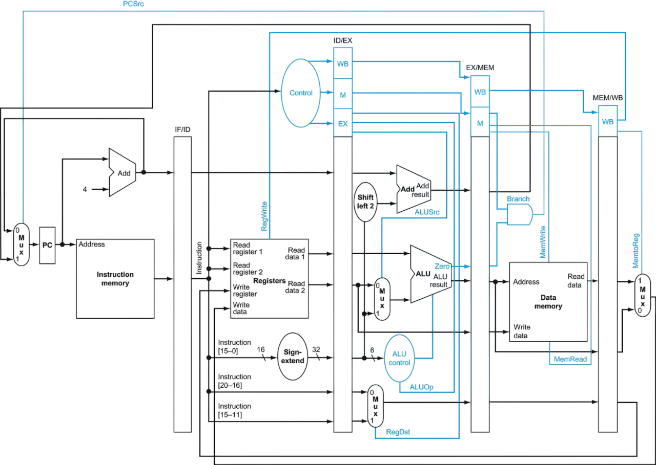
Instruction Fetch (IF)
Fetches instruction from memory using PC
Increments PC by 4
Saves both instruction and incremented PC in IF/ID register
Always active, no special control needed
Instruction Decode (ID) Register File Read
Decodes instruction from IF/ID register
Reads two registers
Sign-extends 16-bit immediate
Generates control signals for later stages
Always active, no special control needed
Execute (EX) Address Calculation
Performs ALU operations
Control signals:
RegDst: Selects destination register
ALUOp: Determines ALU operation
ALUSrc: Chooses between register or immediate value
Memory Access (MEM)
Accesses data memory if needed
Control signals:
Branch: Controls branch operations
MemRead: Enables memory read
MemWrite: Enables memory write
Write Back (WB)
Writes results back to register file
Control signals:
MemtoReg: Selects between ALU result or memory data
RegWrite: Enables register writing
Pipeline Registers
IF/ID
ID/EX
EX/MEM
MEM/WB
64 bits (32-bit instruction, 32-bit PC)
Varies (32-bit immediate, register data, control signals)
128 bits (including data and control signals)
64 bits (including control signals)
- Instruction fetched from memory - Incremented PC (Program Counter)
- Sign-extended immediate - Register numbers - Read data - Control signals for the EX stage
- ALU result - Data to write to memory - Branch target address - Control signals for MEM stage
- Data from memory or ALU result - Destination register number - Control signals for WB stage
Each instruction takes 5 clock cycles to complete
New instruction starts every clock cycle
Up to 5 instructions in pipeline simultaneously
Pipeline Control
EX:
RegDst
ALUOp
ALUSrc
MEM:
Branch
MemRead
MemWrite
WB:
RegWrite
MemtoReg
TODO
branch prediction
Hazards
Structural Hazards
Structural hazard occur when hardware resources are insufficient to support the operations of multiple instructions in the same clock cycle.
Memory Unit
Many simple processor architectures use a single memory unit for both instructions (fetching the next instruction) and data (reading or writing data). A conflict arises if one instruction is fetching an instruction from memory while another needs to access data in the same clock cycle.
Example: The first instruction lw reads from the memory in its MEM stage (CC 4), But, The forth instruction reads (fetch) the instruction from the memory in its IF stage (CC 4 too), that is we use in the same resource (memory, especially reading from it) in the same clock cycle.
Solutions:
Separate memory into two units: instruction memory and data memory, known as Harvard architecture
Cache memory
Stalling
Register File
(Register File) When a specific register is read and written in the same clock cycle, a structural hazard occurs.
# Instruction 1lw $t2, 100($t1) # In WB stage (CC 5) writes to register file ($t2)# ...# Instruction 4add $t7, $t2, $t5 # In ID stage (CC 5) reads from register file ($t2) # The register $t2 is both read and written in the same clock cycle
Solution: Writing will be done in the first half of the clock cycle, and reading in the second half. (Using connecting inverted clock singal to the register file, such that the writting is done in inactive clock edge, relative to the clock of the other components)
(In the study guide: חציית מקבץ האוגרים)
Data Hazards
(1a)EX/MEM.Rd == ID/EX.Rs
(2a)MEM/WB.Rd == ID/EX.Rs
(1b)EX/MEM.Rd == ID/EX.Rt
(2b)MEM/WB.Rd == ID/EX.Rt
Above, in Register File we have seen a situation, where the register is written and read in the same clock cycle, that is Write Register and one of the _Read the Read Registers are the same.
Data hazard: \texttt{\color{lightgreen}\s0}isusedin‘sub‘intheEXstage(cycle3+1=4)beforeitiswrittenintheWBstage(cycle5)of‘add‘.∗∗Forwarding∗∗:Thevalueof\texttt{\color{lightgreen}$s0}$ is available after the EX stage of add (cycle 3) and can be forwarded to the EX stage of sub (cycle 3+1)
Load-Use Data Hazard
Load-Use Data Hazard (resolved by Forwarding & Stalling)
\texttt{lw\ {\color{lightgreen}\s0},20($t1)}\texttt{sub\ $t2,{\color{lightgreen}$s0},$t3}$
Data hazard: \texttt{\color{lightgreen}\s0}is used in `sub` in the EX stage (cycle 3+1=4) before it is written in the MEM stage (cycle 4) of `lw`. (this is a _load-use data hazard_)
Forwarding only is not enough because the value is not available until the MEM stage of `lw` (cycle 4)
**Forwarding & Stalling**: By using in stalling too, the value of\texttt{\color{lightgreen}$s0}$ is available in the EX stage of sub (cycle 3+1+1=5)
Stalling (NOP)
Hazard Detection Unit (HDU) detects the lw instruction in the EX stage, and inserts a NOP (no operation) before the following instruction
Inputs:
ID/EX.RegisterRt (destination register of the lw instruction)
ID/EX.MemRead
Instruction
Outputs:
IF/IDwrite (write to the IF/ID register)
1 = write the instruction in the IF/ID register
0 = prevent writing in the IF/ID register (stall the pipeline)
if (ID/EX.MemRead and
	((ID/EX.RegisterRt = IF/ID.RegisterRs) or (ID/EX.RegisterRt = IF/ID.RegisterRt))
	) then:
	    Stall the pipeline
Reordering Instructions
Reordering Instructions
Both add instructions have a hazard because of the lw instruction (load-use data hazard)
The $t1 in the first lw is used in the add instruction in the EX stage (cycle 3+2=5), but it is written in the WB stage (cycle 5) of the lw instruction
The $t4 in the third lw is used in the add instruction in the EX stage (cycle 3+5=8), but it is written in the WB stage (cycle 5+4=9) of the lw instruction
A control hazard (or branch hazard), occurs when the pipeline must decide whether to branch or not. The decision to branch is made late in the pipeline (during the MEM stage), meanwhile, the pipeline has already fetched the next instructions, which may be executed incorrectly if the branch is taken.
Branch Prediction
Branch prediction: The processor predicts that the branch will not be taken and continue fetching and executing instructions sequentially.
(Branch is not taken) The pipeline continues fetching and executing instructions sequentially
(Branch is taken) The instructions already in the pipeline are discarded, means we must be able to flush instructions in the IF, ID, and EX stages. This done by setting the control values of these stages to zero.
Drawback: If the branch is frequently taken, this approach becomes inefficient because many instructions are discarded
Moving the Branch Decision Earlier
One way to improve branch performance (in the previous solution) is to reduce the cost of the taken branch:
Thus far, we have assumed the next PC for a branch is selected in the MEM stage, but if we move the branch execution earlier in the pipeline, then fewer instructions need be flushed.
Moving the branch decision up requires two actions to occur earlier:
computing the branch target address:
The is the easy part
We already have the PC value and the immediate field in the IF/ID pipeline register, so we just move the branch adder from the EX stage to the ID stage;
of course, the branch target address calculation will be performed for all instructions, but only used when needed
evaluating the branch decision:
This is the harder part
For branch equal, we would compare the two registers read during the ID stage to see if they are equal.
Equality can be tested by first exclusive ORing their respective bits and then ORing all the results. (A zero output of the OR gate means the two registers are equal.)
Difficulties
Forwarding
During ID, we must:
decode the instruction,
decide whether a bypass to the equality unit is needed, and
complete the equality comparison so that if the instruction is a branch, we can set the PC to the branch target address.
Forwarding for the operands of branches was formerly handled by the ALU forwarding logic, but the introduction of the equality test unit in ID will require new forwarding logic.
Note: the bypassed source operands of a branch can come from either the ALU/MEM or MEM/WB pipeline latches.
Hazards
Moving the branch test to the ID stage implies additional forwarding and hazard detection hardware, since a branch dependent on a result still in the pipeline must still work properly with this optimization.
For example, to implement branch on equal (and its inverse), we will need to forward results to the equality test logic that operates during ID.
Because the values in a branch comparison are needed during ID but may be produced later in time, it is possible that a data hazard can occur and a stall will be needed.
For example, if an ALU instruction immediately preceding a branch produces one of the operands for the comparison in the branch, a stall will be required, since the EX stage for the ALU instruction will occur after the ID cycle of the branch.
By extension, if a load is immediately followed by a conditional branch that is on the load result, two stall cycles will be needed, as the result from the load appears at the end of the MEM cycle but is needed at the beginning of ID for the branch.
Summary
Despite these difficulties, moving the branch execution to the ID stage is an improvement, because it reduces the penalty of a branch to only one instruction if the branch is taken, namely, the one currently being fetched.
The exercises explore the details of implementing the forwarding path and detecting the hazard.
To flush instructions in the IF stage, we add a control line, called IF.Flush, that zeros the instruction field of the IF/ID pipeline register.
Clearing the register transforms the fetched instruction into a nop, an instruction that has no action and changes no state.
Dynamic Branch Prediction
Total Stalls=IC×B×M×S
B is the fraction of branches
M is the fraction of mispredictions of the BPU (=1−Accuracy)
S is the stall cost (penalty)
IC is the number of instructions
Total Stalls is the total number of stalls in the pipeline